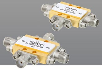
A Radio Frequency mixer is a three-port passive or active device that combines two or more signals into one or two composite output signals, and is the backbone of heterodyne and superheterodyne communications technologies. The purpose of a mixer is to produce a signal at a new frequency, while preserving other characteristics of the initial signal for reception or transmission. Conceptually, the three ports on a mixer are the radio frequency (RF) port, the local oscillator port (LO), and the intermediate frequency port (IF). The RF port is where the high frequency signal is applied to down-convert it, or where the high-frequency signal is output in an upconverter. The local oscillator (LO) port is where the power is applied. The LO signal is the strongest signal and turns the diodes on and off in a switching mixer which then reverses the path of the RF to the IF. In other words, the IF port is where the modified RF signal is manipulated to become the IF signal.
While the mixer operates within its linear range, increases in IF output power corresponds to increases in RF input power. Conversion compression occurs outside the linear range. The 1-dB compression point is where the conversion-gain is 1dB lower than the conversion gain in the linear region of the mixer. The LO power coupled into the mixer controls performance. Inadequate LO power for a given mixer degrades conversion-gain and noise figure and, therefore, system sensitivity. Conversion gain factor is specified at a particular LO drive level and is defined as the ratio of the numeric single-sideband (SSB) IF output-power to the numeric RF input-power such that a positive value for an IF output-power greater than the RF input-power indicates conversion gain. Conversely, a negative result occurs for conversion loss. A mixer’s performance is determined by several metrics with conversion loss as the benchmark mixer metric as it correlates closely with other metrics like isolation and 1 dB compression. Other key mixer parameters include Intermodulation Distortion (IMD) and Local Oscillator (LO).
Conversion loss is the difference in signal level between the amplitude of the input signal and the amplitude of the desired output signal. In a mixer used for downconversion, the conversion loss is the difference between the RF input signal’s amplitude and the IF output signal’s amplitude. In a mixer used for upconversion, the conversion loss is the difference between the IF input signal’s amplitude and the RF output signal’s amplitude. A mixer’s conversion loss remains constant when the mixer is in linear operation. As the amplitude of the input signal increases, the amplitude of the output signal rises by the same amount. However, once the input signal’s amplitude reaches a certain level, the amplitude of the output signal ceases to exactly follow the input signal. The mixer deviates from linear behavior and its conversion loss begins to increase.
Noise figure (NF) is the added noise generated by the mixer and present at the IF output, the noise figure is the second important parameter for the passive filter. For a passive mixer, the NF is almost equal to the loss.
Isolation is the amount of power that leaks from one port to another and understood as the difference in signal level between the amplitude of an input signal and the amplitude of the leaked power from that input signal to another port so that when isolation is high, the amount of power leaked from one port to another is small. The three important isolation points to consider in your system are RF to IF, LO to IF, and LO to RF. The LO presents a problem because it is usually a much stronger signal that the other two. The problem with LO (or RF) at the IF terminal is that these signals may cause other spurious products later in the chain and saturate the IF amp if they are strong enough. The problem with LO at the RF port is that it can cause your receiver to radiate RF energy at the antenna port.
1-dB Compression point occurs when a mixer’s conversion loss increases by 1 dB and is defined as the amplitude of the input signal required to increase the conversion loss by 1 dB. A mixer’s 1-dB compression point determines the upper limit of its dynamic range. A mixer’s 1-dB compression point is usually related to the LO drive level. Mixers with higher LO drive level requirements have a higher 1-dB compression point and require increased power. In general, the 1-dB compression point is anywhere from 4 to 7 dB below the mixer’s minimum recommended LO drive level.
Intermodulation Distortion (IMD) occurs when signals simultaneously enter the mixer’s IF or RF input port. The signals interact with each other and with the LO signal creating distortion. In a receiver, two-tone third-order IMD is a serious problem because it can generate third-order distortion products that fall within the IF bandwidth. A major goal in mixer design is to limit the strength of the single-tone IMD. Multi-tone IMD implies that multiple tones enter the mixer through the same port and are subject to nonlinearities in the mixer diodes. Multi-tone IMD is a form of common mode mixing in which two or more tones enter the RF port and nonlinearly mix with each other and the LO to create distortion.
Local oscillator (LO) is a reference signal required for mixer injection to facilitate frequency translation in the receiver system. The local oscillator signal mixes with the desired RF signal to produce an IF. The sum (LO+RF) and difference (LO–RF or RF–LO) terms are output to the IF mixer port. The oscillator frequency is tuned to select a desired frequency to be down-converted to an intermediate frequency. Once the oscillator is tuned, a signal that has the same spacing as the IF frequency away from the LO frequency is down-converted and passed through the IF filter. Key specifications for an LO include tuning range, frequency stability, spurious output levels, lock-time, and phase noise.

